Introduction
When final reconstruction of the bridge is complete, almost all traces of the temporary cradle will have been removed. The photos on this and an accompanying page, taken by John Field and Shirley Moon, will be the primary record of this important step in saving the covered bridge at Bridgeport.
Underside of the South End of the Bridge
Underside of the south end of the bridge (Visitor Center end) just before beginning cradle construction in earnest.
(September 18, 2014, contractor: Camblin Steel Service, Inc., Rocklin, CA; 916-644-1300)
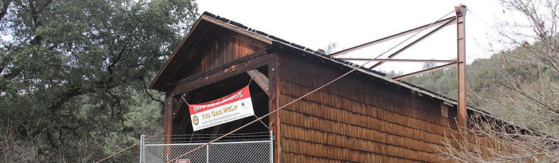
Underside of the North End of the Bridge
Forms for South-end Piers.
Zoomed View
In this zoomed view of the far end you can see a cross beam of the cradle (mostly in shadow, tucked under the bridge) and the concrete piers on the shoreline on which the columns are secured.
Concrete Piers
Concrete piers after forms were removed.
Modern Bridge
Modern bridge in background confirms this is the south end of the bridge.
Enormous Hole
Enormous hole dug at south end for high-strength steel rod anchors.
Concrete Trucks
Three trucks full of concrete to fill the hole.
Pumping Concrete
Begin pumping concrete into the hole
Pumping Continues
Continue pumping. Note the rebar cage for one of the steel rod anchors, which will be included in the pour.
The purpose of the massive block of concrete is to provide mass and friction for the anchors.
Still Pouring
Still pouring Note the anchor rebar cages aligned with each side of the bridge.
(December 19, 2014)
Concrete Pour Complete
 (Large).JPG)
Concrete pour is complete and partly cured. Note that the cable anchor cages had concrete forms added during the pour.
(January 13, 2015)
Steel Stack
 (Large).JPG)
Stack of ASTM A36 (36-ksi strength) steel pre-cut members to create the cradle.
Also note the threaded rods which will form the "cables" from the anchors.
Cradle Cross Beams
.JPG)
One of the four cradle cross beams in place above the north-end piers
Construction Drawing
Construction drawing for the cradle. The end views show the bridge cross section cradled between columns on each side.
Four cross beams at the base of the bridge will carry the bridge.
Drawing Close-up
This close-up of the south end of the bridge shows the locations of the two cross beams at this end (one at the south column, and the other where a rod comes down from from the top of the south column to attach to the cross beam).
The beams are called out as W 12x53 beams, which means a nominally 12-inch H section of ASTM A36 steel (nominal 36-ksi yield strength) weighing 53 lbs/ft.
The rods are 150-ksi-strength 1.25-inch diameter threaded rods assembled by means of threaded "turnbuckle" connectors.
This will become more clear in photographs to come.
Mirror Image
Mirror image construction at the north end of the bridge.
Temporary Support
Cross beam and its temporary support from the south piers
South Cross Beam Close-up
Close-up of the south cross beam and its connection plate to be bolted to the southwest column
Two of Columns
Two of the four columns ready for pre-assembly into a column pair