Introduction
When final reconstruction of the bridge is complete, almost all traces of the temporary cradle will have been removed. The photos on this and an accompanying page, taken by John Field and Shirley Moon, will be the primary record of this important step in saving the covered bridge at Bridgeport.
A Column
A fork lift carries a column into place for pre-assembly of the south column pair.
(February 4, 2015)
Cross Member
A cross member is bolted at the top of a column
Cross Member In Place
Complete X Frame
Complete X frame at the top of the column pair
Huge Crane
A huge crane picks up the south end column pair to carry it to the bridge.
Nearly Vertical
Nearly vertical. The outward splaying at the top is part of the design, not an optical illusion.
(see the drawing in Part 1).
Columns Not Connected
At this point, the columns are not connected to the X frame at its bottom, so the columns can spread around the bridge during assembly.
The Spreading
The spreading is even more apparent in this photo.
Roof
A bit of the roof had to be removed as the columns were lowered onto the south piers.
Workman
Workman now has access to the bottom beam of the X frame.
Mating Columns
Mating the columns to their piers.
Continuing The Alignment Process.
Portable Come-Along
A portable come-along was used to pull the column into position, where it was bolted to its pier.
(February 4, 2015)
Tie Rods
 (Large).JPG)
Tie rods were then connected to their anchors the next day.
Column Tops
 (Large).JPG)
...from the tops of the columns
View From Modern Bridge
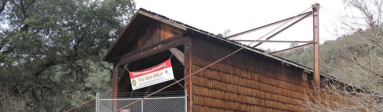
 (Large).JPG)
Zoomed view from the modern bridge upstream. The cables going from these south columns to the north columns were used only during the assembly process.
Procedures
 (Large).JPG)
Similar procedures were used to install rod anchors and columns at the north end of the bridge
Final Connections
 (Large).JPG)
Final connections between the columns, via the intermediate bridge support beams, were done with high-strength threaded rods, just as for the connections of the column tops to their shoreside anchors.
The net vertical force that can be applied to each intermediate cross beam by the tie rods is about 150,000 lb within the 150-ksi strength of the rods. Actual loads will be much less.
(February 21, 2015)
Another View
 (Large).JPG)
Another view of connections to the north intermediate cross beam.
Columns And Tie Rods
 (Large).JPG)
Columns and tie rods along the east side of the bridge.